Autonomous robotic navigation with TIAGo robot ROS Simulation Tutorial
The second pack of open-source ROS tutorials for TIAGo’s simulation in Gazebo enables the robot to navigate autonomously in indoor spaces. Learn how to create a map with gmapping, localize itself in the space and do path planning avoiding obstacles in real time with the TIAGo Tutorials. PAL Robotics team puts available tutorials in TIAGo robot navigation among other tasks that TIAGo can perform in its public simulation to make it accessible for everyone interested.
Creating a map with gmapping
TIAGo can create a map of the environment around it by using the laser range-finder on the base. The map is required to use afterward AMCL based localization to match laser scans with the map to provide reliable estimates of TIAGo’s pose in the map. All steps are detailed on the Tutorial in order to map the area commanding TIAGo with the keyboard. After completing the map, it can be saved and can be used to perform autonomous localization and path planning. This is an example on how the map is created by TIAGo:
Localization and path planning
Make TIAGo locate itself and plan a path between two points of interest with the second part of the ROS Navigation Tutorials for TIAGo. This tutorial shows how to make TIAGo navigate autonomously provided a map. The collaborative robot is able to detect and avoid obstacles using the base laser and the RGB-D camera on its pan-tilt head.

ROS Tutorial 2: TIAGo localization in simulation.
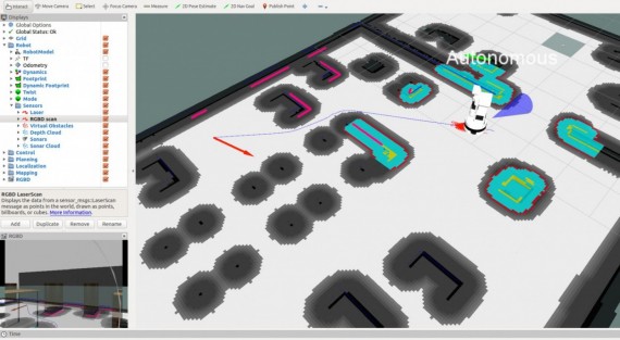
First, the built up of laser scans map should be created using the previous mapping Tutorial. Second, the map created in the previous tutorial should be opened following the steps here, which will show it in rviz as a result. Different kinds of information will be overlaid on top of the map, amongst others:
- Particle cloud: a cloud of small red arrows representing the amcl filter particles, which spreads around the robot. A concentration of the particles indicates growing confidence in its position estimate.
- Global costmap: regions around obstacles which are used by the global planner in order to compute paths to navigate from one point of the map to another without getting too close to the static obstacles registered during mapping. More details can be found here.
- Local costmap: similar to the global costmap, but it is smaller and moves with the robot, it is used to take into account new features that were not present in the original map. It is used by the local planner to avoid obstacles, both static and dynamic while trying to follow the global path computed by the global planner. More details can be found here.
- Laser scan: lines in dark blue represent the points measured with the laser of the mobile base. This scan is used to add/remove obstacles both in the global and local costmaps.
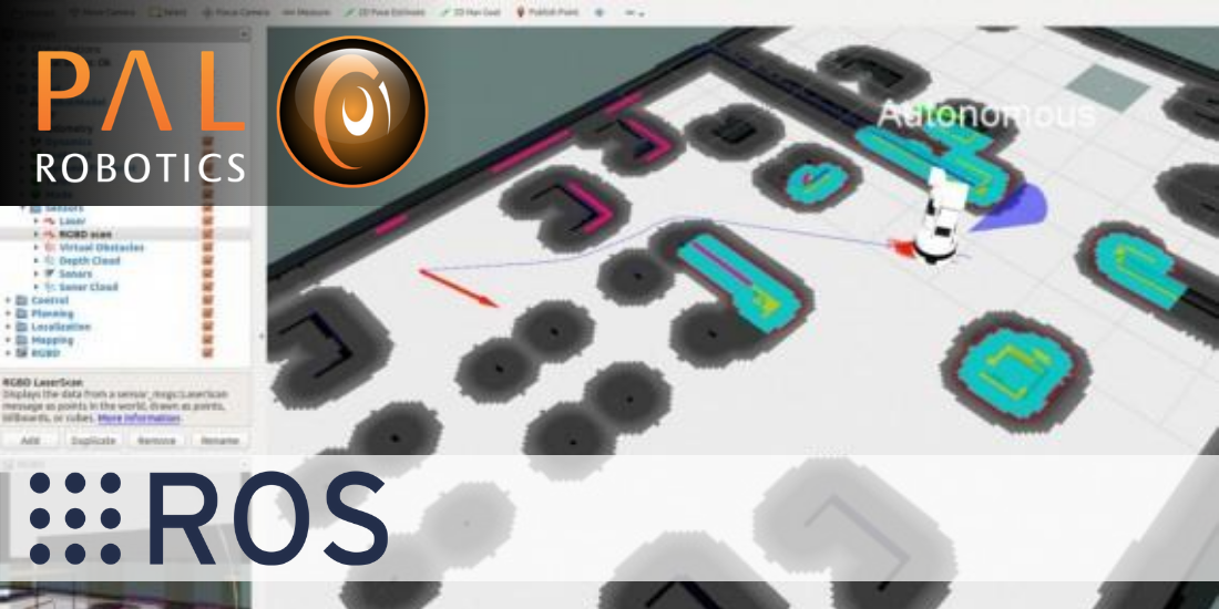
- RGBD scan: lines in magenta represent the projection of the point cloud reconstructed by the RGBD camera of the head onto the floor. This artificial scan is also used to add/remove obstacles to the global and local costmaps. This scan is useful to obtain a 3D information of the environment, detecting obstacles that are higher or lower than the laser scanner plan.
ROS Tutorial 2: Autonomous TIAGo robot navigation path.
All this information is used as described in the Tutorial to enable TIAGo to locate itself correctly in the given space. Besides, this enables as well the TIAGo autonomous navigation with rviz, that sends the robot to a desired point that it needs to reach. The action should be completed through the shortest path and avoiding obstacles as well.
We want to see your developments!
Find other tutorials on Control, MoveIt!, Open CV and PCL at TIAGo’s ROS Wiki, which will be detailed soon in our blog as well. Share your awesome results with us and don’t miss our updates and news with our blog!